
Browse this field: Electrochemistry
Product overview
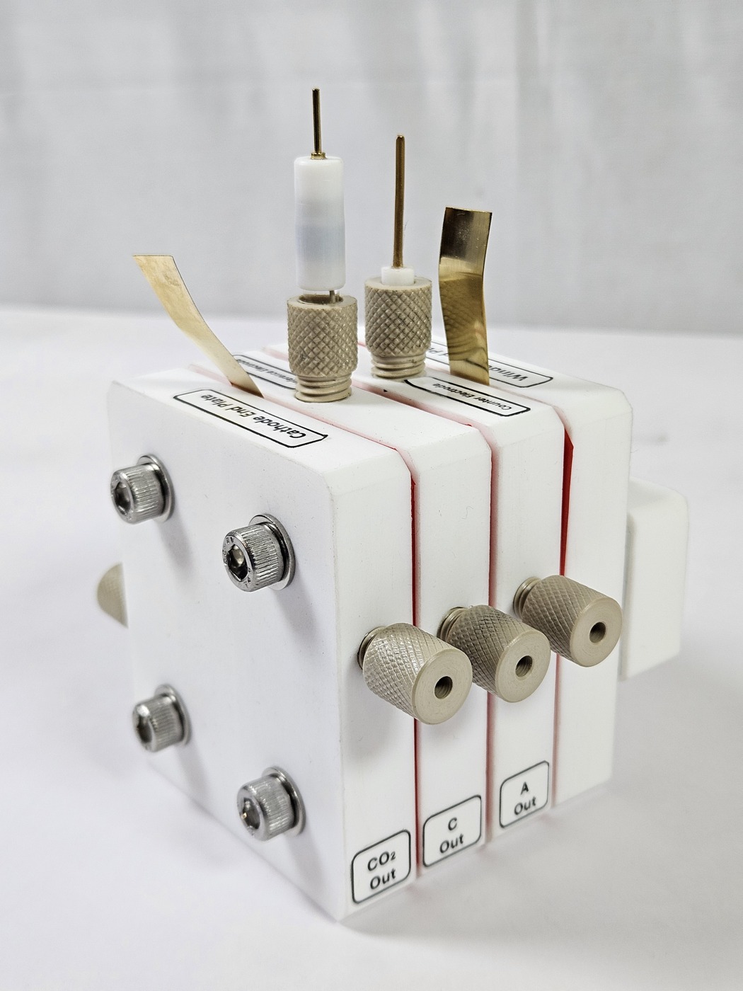
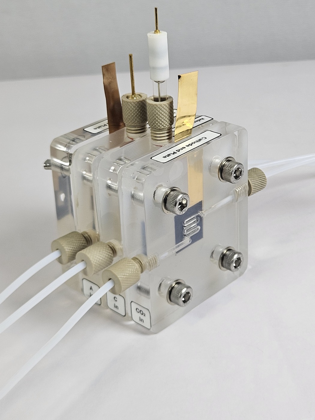
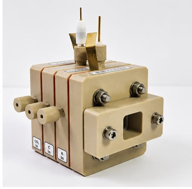
The CF-T uses a PTFE body for three-electrode CO₂ reduction studies. CO₂ reaches the rear face of the catalyst-coated gas-diffusion electrode, while the membrane separates the two liquid circuits. Specify active area, chamber volume, flow-field geometry, seals and fittings together. Reference/counter electrodes, membrane, catalyst-coated GDEs, pumps and analytical instruments depend on the selected quotation package.
Specifications & ordering details
Use these parameters to define your requirement. The quotation confirms the exact supplied specification.
| System / method | CO₂ reduction research hardware |
|---|---|
| Body | PTFE |
| Working dimensions | 1 × 1 / 2 × 2 / 3 × 3 / 5 × 5 / 10 × 10 cm |
| Geometric active areas | 1 / 4 / 9 / 25 / 100 cm², respectively |
| Liquid chamber volume | 1.5–250 mL per chamber, configuration dependent |
| Flow channels | Serpentine / parallel / interdigitated / customized |
| Electrode options | Ag/AgCl reference and Pt spring counter; selected package |
| Model coding | CF-[body]-[area in cm²], e.g. CF-T-25 for 25 cm² |
| Experiment or process requirements | Specify with your requirement. |
| Operating range and sample / DUT dimensions | Specify with your requirement. |
| Interfaces, options and included accessories | Specify with your requirement. |
Research applications
- CO₂ reduction catalyst screening
- Membrane and mass-transport studies
- Three-electrode gas-diffusion experiments
Before you order
- Specify body chemistry, active area and liquid chamber volume.
- State membrane, GDE, reference/counter electrodes and wetted-material needs.
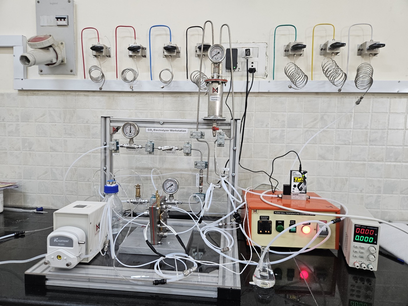
- List flow-field pattern, connections and pump/analysis scope.
Product documents
View the source catalog for this offering. Share your instrument model, configuration and application to request the relevant specification or material documentation.
View CO₂RR Flow Cells & Workstations — page 1 ↗Download PDFSelection questions
How do I check the instrument interface?
Share the instrument make and model, sample geometry, optical or beam path, mounting arrangement and drawings. The cell and instrument interfaces must be reviewed together.
Which experimental conditions are needed?
Specify temperature, pressure, atmosphere or electrolyte, and electrical connections. Confirm sample access, windows, fittings and accessories for the selected method.
 CF-A PMMA CO₂RR Flow Cell
 CF-K PEEK CO₂RR Flow Cell
 CW-A PLC/HMI Automated CO₂RR Workstation
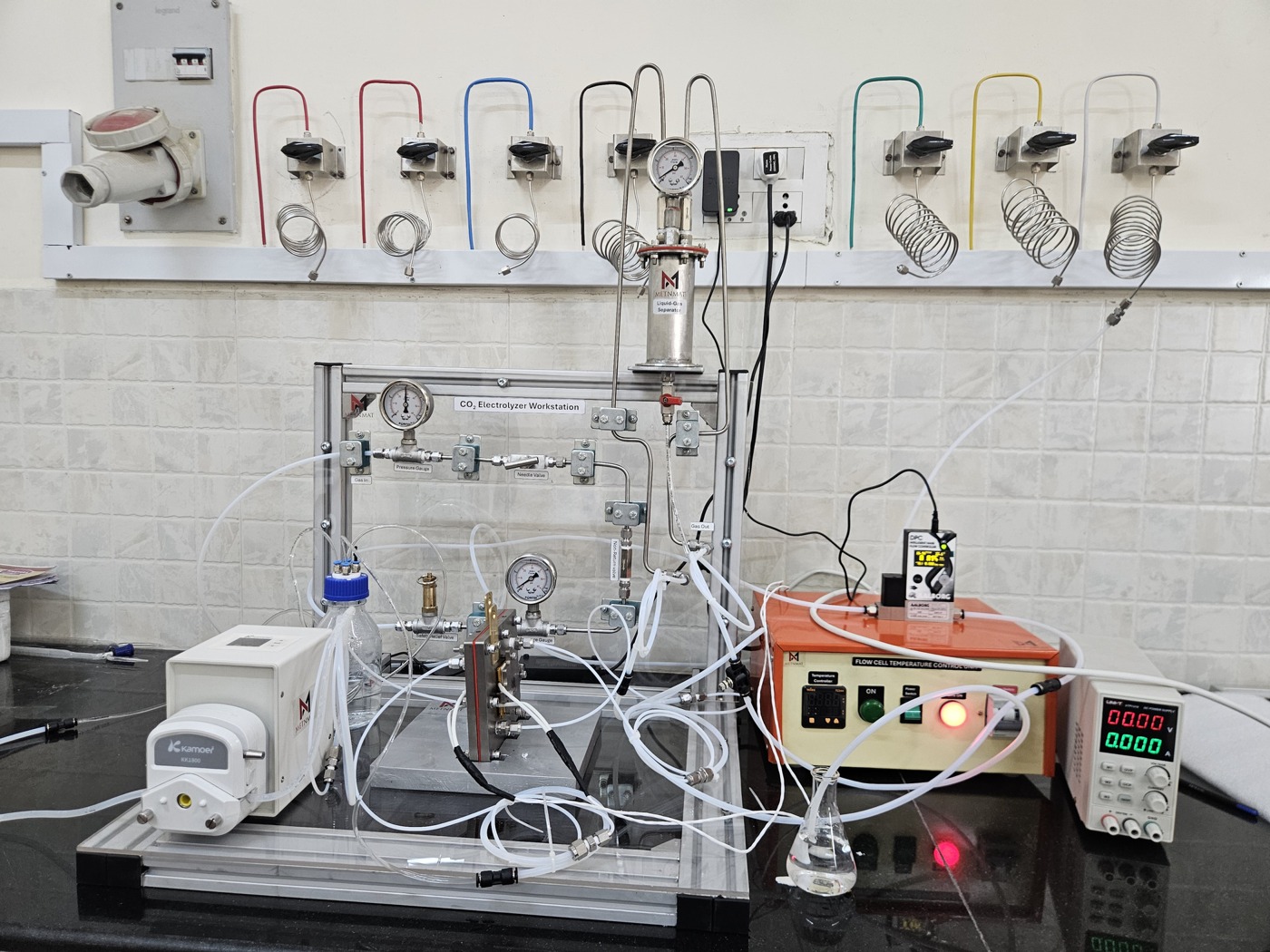 CW-B Benchtop CO₂RR Workstation